In this tutorial, you'll learn the basics of working with DataObjects for .NET, including how to:
- Import a database structure so it becomes a data schema, the basis of all DataObjects for .NET activities.
- Create composite tables, to better shape and represent data to meet the needs of your users.
- Specify business logic in the form of calculation expressions and constraints. Note that in this tutorial, you'll specify business logic using calculated expressions and constraints. More business logic features will be introduced in other tutorials.
- Create data set definitions (DataSetDef) consisting of TableView objects exposing data to the user.
- Bind graphic user interface (GUI) controls to a DataObjects for .NET data source.
In this tutorial you'll use two different data bound grid controls, TrueDBGrid for .NET and Microsoft DataGridView, to demonstrate that DataObjects for .NET can serve as a data source to any data-bound GUI controls adhering to .NET databinding specifications. All other tutorials will use only ComponentOne grid controlsas they are most closely integrated with DataObjects for .NET. Most DataObjects for .NET features, all features that rely only on standard .NET data binding, will work with any third-party data-bound control. However, some DataObjects for .NET features that are extensions of standard .NET data binding, most notably, Virtual Mode (see Tutorial 4: Virtual Mode: Dealing with Large Datasets), require that you use ComponentOne data bound controls.
The first step in using DataObjects for .NET is creating a data schema. A schema is created using the DataObjects Schema Designer. Unlike in standard ADO.NET, a schema and associated business logic can be created once and then reused throughout your projects. Normally, you create a new schema by importing a database structure using the schema designer's Import Wizard. Alternatively, you can import an existing ADO.NET schema. See Converting Schema from Other Sources for more information.
To set up the project and create a schema:
- Create a new Windows Application project.
- Place the following components on the form as shown in the image below.
Number of Components Names Namespace 1 C1SchemaDef C1SchemaDef1 C1.Data.C1SchemaDef 2 C1DataSet C1DataSet1
C1DataSet2C1.Data.C1DataSet 2 C1TrueDBGrid C1TrueDBGrid1
C1TrueDBGrid2C1.Win.C1TrueDBGrid.C1TrueDBGrid 1 Label Label1 System.Windows.Forms.Label 1 DataGridView DataGridView1 System.Windows.Forms.DataGridView 2 command Buttons Button1
Button2System.Windows.Forms.Button
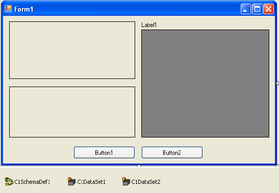
- Set the Text property of Button1 to "Commit Changes" and the Text property of Button2 to "Products and Orders".
- Select the C1SchemaDef1 control, use the smart tags to expand the C1SchemaDef Tasks menu and select Schema Designer.
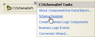
The Schema Designer opens, and the Import Wizard appears.
Note: Select Schema | Import database structure in the Schema Designer to open the Import Wizard if it does not automatically appear.
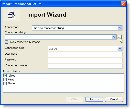
- In the Import Wizard dialog, click the ellipsis button
 to the right of the connection string. The standard OLE DB Data Link Properties dialog box opens.
 - Select the provider, the database and other necessary connection properties in that dialog box. In this tutorial, the standard MS Access Northwind sample database (C1NWind.mdb) is used.
- Click the Provider tab, if necessary, and select Microsoft Jet 4.0 OLE DB Provider.
- Click the Connection tab and then click the ellipsis button under Select or enter a database name.
- Locate the C1NWind.mdb database, installed by default in the Common folder in the ComponentOne Samples directory, and click Open.
- Click OK to close the DataLink Properties dialog box. The connection string is imported.
- Click Next. In this window, you can select the tables to import into the schema.
- Click the
 button to select all available tables and then click Finish. The Import Wizard creates the schema and closes.
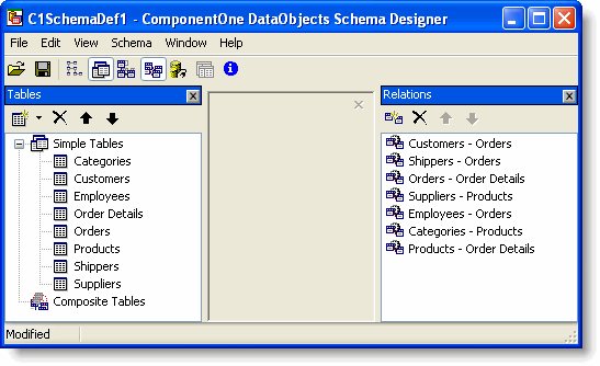
In the Schema Designer, the Tables window contains the list of all simple tables created by the Import Wizard based on the database tables. The Relations window contains inter-table relations created by the Import Wizard based on the relationships existing in the database.
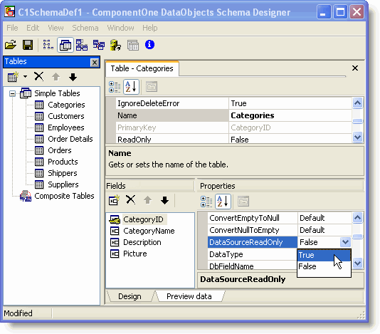
- Double-click the Categories table in the Tables window and select the CategoryID field from the Fields list in the lower panel of the Table Editor.
- Set its DataSourceReadOnly property to True. Note that modifying table properties is only necessary when you use Microsoft Access as your database, since the MS Access OLE DB provider does not consider Autoincrement fields (row identity fields; their values are automatically assigned and maintained by the database) as read-only.
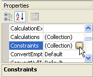
Note: Switch between the Design and Preview data views of the tables using the tabs at the bottom of the editor window or by using the Shift and F5 keys; press F5 to move from Design to Preview data view or press Shift+F5 to move from Preview data to Design view. - Double-click the Products table in the Tables window and select the UnitPrice field from the Fields list in the lower panel of the Table Editor.
- Click the ellipsis button next to the Constraints property to open the Constraints Editor.
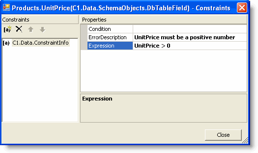
- Click the Add button
 . A constraint is added to the list, and its properties appear in the right pane of the Constraints Editor. Note that a field can have multiple constraints.
- Type the following expression in the Expression property:
UnitPrice > 0 - Add the following string in the ErrorDescription property:
UnitPrice must be a positive number
- Type the following expression in the Expression property:
- Click Close. The constraint expression for the UnitPrice field of the Products table is specified, and now we will create several composite tables.
To create composite tables:
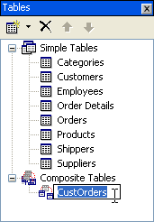
- In the Schema Designer, right-click the Tables window and select Add | Composite Table from the context menu.
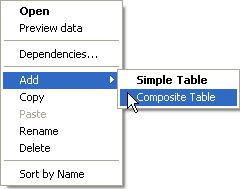
- In the newly added node, change the default name from CompositeTable to "CustOrders".
The Composite Table Editor opens when a new composite table is created. The editor has two tabs: Diagram and Properties. Using the Diagram tab, you can specify which simple tables are used in the composite table and how they are related.
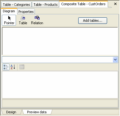
- Click the Add tables button at the top of the editor. The Add Tables dialog box opens.
- Select Customers,OrdersandEmployees in the Existing tables window and click the
 button to move them to the Selected tables window.
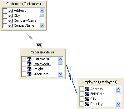
 - Click OK. A diagram is created and consists of three tables connected by two relations. Note that it may be necessary to expand your Diagram display pane to see the tables.
- Select Customers,OrdersandEmployees in the Existing tables window and click the
- The relation between Orders and Employees must be inverted, because we need an employee record (child record) to be uniquely determined by an order record (parent record); currently Employees is the parent and Orders is the child. Right-click the Orders – Employees relation on the diagram, and select Invert from the context menu. This makes Orders the parent and Employees the child.
-
Rename the relation correspondingly: with the relation selected, set its Name property to Orders – Employees in the property grid below the diagram.
The structure of the composite table CustOrders shown on the diagram can be represented in the following notation:
Customers →(1-∞) Orders →(∞-1) EmployeesHere →(1-∞) is a one-to-many relation, and →(∞-1) is a many-to-one relation. Relation cardinality, either OneToMany or ManyToOne, can be seen on the diagram (the infinity symbol designates the many part) and in the property grid when the relation arrow is selected.
According to relation cardinality, each row of the CustOrders composite table consists of a Customers row, an Orders row (one of the child rows of the Customers row) and an Employees row (the single child row uniquely determined by the Orders row).
- To create the fields in our new CustOrders composite table, select fields in the constituent tables in the diagram:
- Select the Customers table and check the checkboxes for the following fields: Address, City, Country, CustomerID, PostalCode, and Region.
- Select the Orders table and check the checkboxes for all fields except CustomerID. The CustomerID is used in the Customers – Orders relation to connect an order record to a customer record; it has no other purpose, and CustomerID is already selected in the Customers table.
- Select the Employees table and check the checkboxes for the following fields: FirstName and LastName. EmployeeID is not included for the same reason the CustomerID field was not included in the Orders table.
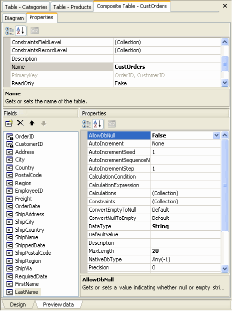
Note: To view all fields and their properties, select the Properties tab in the Composite Table Editor. Each field that was checked appears in the lower panel.
- In the same way we created the CustOrders table, create another composite table, OrderDetailsProducts, by combining the simple tables Order Details and Products.
- Right-click the relation between Products and Order Details and select Invert.
- Set the relation's Name property to Order Details – Products in the property grid below the diagram.
- Select the Order Details table and check the checkboxes for all fields except UnitPrice.
- Select the Products table and check the checkboxes for ProductName and UnitPrice.
The resulting OrderDetailsProducts composite table has the following structure:
Order Details →(∞-1) Products
A row of the OrderDetailsProducts composite table consists of an Order Details row and a Products row (the single child row uniquely determined by the Order Details row).
- Add a new calculated field, ExtendedPrice, to the OrderDetailsProducts composite table:
- Select the Properties tab of the Composite Table Editor.
- Right-click the Fields list and select Add from the context menu. A new CompositeTableField is added to the list.
- Change the default name to ExtendedPrice.
- With the ExtendedPrice field selected, enter the following value in the CalculationExpression property:
Quantity * UnitPrice * (1 - Discount)
-
Set the DataType property to Decimal.
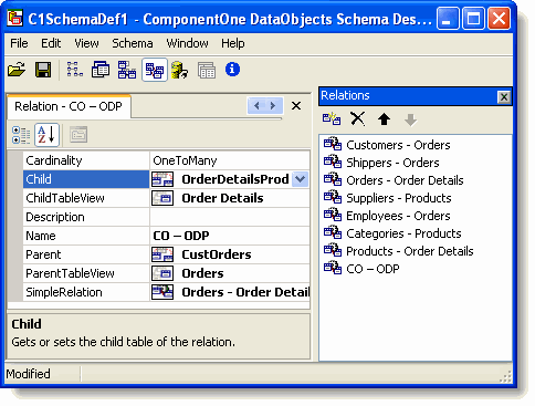
Note: Calculated fields can be added to simple tables as well as to composite tables. See Table Fields for details. - We are going to create a composite relation between the CustOrders and OrderDetailsProducts composite tables. Right-click anywhere in the Relations window and select Add from the context menu. The Relation Editor appears.
- Rename the relation CO – ODP, short for CustOrders – OrderDetailsProducts.
- Click the drop-down arrow next to the Parent property and select CustOrders from the list of all available tables.
- Click the drop-down arrow next to the Child property and select OrderDetailsProducts from the list of all available tables.
When you select a composite table in the Parent or Child property, the Relation Editor changes. The JoinConditions panel disappears, and the set of properties changes, all due to the fact that the relation is now a composite relation not a simple relation. A composite relation, or a relation between two tables, one of which is a composite table, is based on a simple relation that connects two tables, one belonging to the parent composite table and the other belonging to the child composite table.
To create data sets:
- In the Schema Designer, select View | DataSets so the DataSets window is visible.
- Right-click anywhere in the DataSets window and select Add in the context menu.
- Change the default name to CustOrders.
- In the DataSet Editor, click the Add tables button. The Add Tables dialog box opens.
- Select CustOrders,OrderDetailsProducts andEmployees in the Existing tables window and click the button to move them to the Selected tables window. Note that CustOrders andOrderDetailsProducts are composite tables. Employees is a simple table.
- Click OK. A diagram is created and consists of three tables; CustOrders and OrderDetailsProducts are connected by a relation. Note that it may be necessary to expand your Diagram display pane to see the tables.
- Select CustOrders,OrderDetailsProducts andEmployees in the Existing tables window and click the
- Right-click the Employees table and choose Fields from the context menu. The Fields Editor appears.
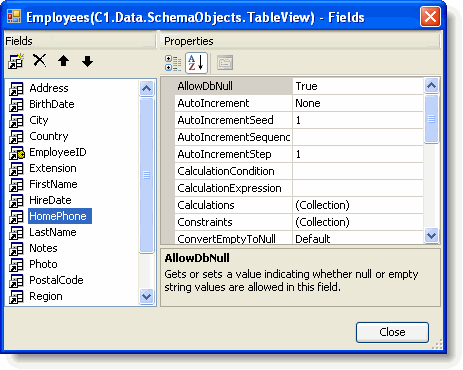
- Select a field and use the Move up and Move down arrow buttons to re-arrange the field order.
- Click Close.
- To demonstrate how multiple data sets can exist in a schema, create one more data set with two composite tables. First, create the composite tables:
- Add a new composite table and name it CustOrdersDetails:
- Click the Add tables button and add the following tables: Customers, Orders, Order Details,Products and Categories.
- Invert the relation between Products and Order Details and rename it Order Details – Products.
- Invert the relation between Categories and Productsand rename it to Products - Categories.
- Select the Customers table and check the checkboxes for the following fields: Address, City, CompanyName, Country, CustomerID, PostalCode and Region.
- Select the Orders table and check the checkboxes for all fields except CustomerID.
- Select the Order Details table and check the checkboxes for the following fields: Discount, ProductID and Quantity.
- Select the Products table and check the checkboxes for the following fields: CategoryID, ProductName and UnitPrice.
- Select the Categories table and check the checkboxes for the following fields: CategoryName.
The resulting CustOrdersDetails composite table has the following structure:
Customers →(1-∞) Orders →(1-∞) Order Details →(∞-1) Products →(∞-1) CategoriesA row of the CustOrdersDetails composite table consists of a Customers row, an Orders row (one of the child rows of the Customers row), an Order Details row (one of the child rows of the Orders row), a Products row (the single child row uniquely determined by the Order Details row) and a Categories row (the single child row uniquely determined by the Products row).
- Add a second composite table and name it ProductsOrderDetailsCust:
- Click the Add tables button and add the following tables: Customers, Orders, Order Details, Products and Categories.
- Invert the relation between Categories and Productsand rename it to Products - Categories.
- Invert the relation between Orders and Order Detailsand rename it to Order Details - Orders.
- Invert the relation between Customers and Ordersand rename it to Orders - Customers.
- Select the Products table and check the checkboxes for the following fields: CategoryID, ProductID, ProductName, UnitsInStock and UnitsOnOrder.
- Select the Categories table and check the checkboxes for the following fields: CategoryName.
- Select the Order Details table and check the checkboxes for the following fields: OrderID and Quantity.
- Select the Orders table and check the checkboxes for the following fields: CustomerID.
- Select the Customers table and check the checkboxes for the following fields: CompanyName.
The resulting ProductsOrderDetailsCust composite table has the following structure:
Products →(1-∞) Order Details →(∞-1) Orders →(∞-1) Customers;
Products →(∞-1) Categories
Note the branching at the Products node. It has two children: Order Details connected with a one-to-many relation and Categories connected with a many-to-one relation. In general, branching in composite table diagrams is allowed, but only for many-to-one relations. One-to-many relations are not allowed to branch in a composite table, because a composite table should not form a branched tree; it must contain a set of rows having identical structure.
A row of the ProductsOrderDetailsCust composite table consists of a Products row, a Categories row (the single child row uniquely determined by the Products row), an Order Details row (one of the child rows of the Products row), an Orders row (the single child row uniquely determined by the Order Details row) and the Customers row (the single child row uniquely determined by the Orders row).
- Add a new composite table and name it CustOrdersDetails:
- Finally, create a DataSet, ProductsOrders, including two composite tables, CustOrdersDetails and ProductsOrderDetailsCust:
- Right-click anywhere in the DataSets window and select Add in the context menu.
- Change the default name to ProductsOrders.
- In the DataSet Editor, click the Add tables button. The Add Tables dialog box opens.
- Select CustOrdersDetails andProductsOrderDetailsCust in the Existing tables window and click the button to move them to the Selected tables window.
- Click OK. A diagram is created and consists of two tables. Note that it may be necessary to expand your Diagram display pane to see the tables.
- The schema is ready. Select File | Save As, enter Schema1 in the File name text box and click Save. This schema will be used in other tutorial projects.
- Close Schema Designer and click Yes if asked whether you want to save changes. The schema is saved in the C1SchemaDef1 component (in the form resource file).
- In your project, set the SchemaDef property of C1DataSet1 and C1DataSet2 to SchemaDef1. This connects the data set components to the schema.
- Choose the data set exposed by each of the two components:
- Set the DataSetDef property of C1DataSet1 to CustOrders.
- Set the DataSetDef property of C1DataSet2 to ProductsOrders.
- A client application usually needs some subset of data fetched to a data set, so we need some means of restricting, or filtering, data as it is retrieved from the database. This can be done by using FilterConditions. In this tutorial, we will restrict product data to only those products that have CategoryID = 1 (beverages) in C1DataSet2, the ProductsOrders data set, using the BeforeFill event. C1DataSet1, the CustOrders data set, will remain unrestricted. Add the following code to create the C1DataSet2_BeforeFill event handler to restrict product data:
To write code in Visual Basic
Visual Basic Copy CodePrivate Sub C1DataSet2_BeforeFill(ByVal sender As Object, ByVal e As C1.Data.FillEventArgs) Handles C1DataSet2.BeforeFill Dim dataSetDef As C1.Data.SchemaObjects.DataSetDef dataSetDef = e.DataSet.Schema.DataSetDefs("ProductsOrders") e.Filter.Add(New C1.Data.FilterCondition(dataSetDef.TableViews_ ("ProductsOrderDetailsCust"), "[CategoryID] = 1")) e.Filter.Add(New C1.Data.FilterCondition(dataSetDef.TableViews _ ("CustOrdersDetails"), "[CategoryID] = 1")) End SubTo write code in C#
C# Copy Codeprivate void c1DataSet2_BeforeFill(object sender, C1.Data.FillEventArgs e) { C1.Data.SchemaObjects.DataSetDef dataSetDef = e.DataSet.Schema.DataSetDefs["ProductsOrders"]; e.Filter.Add(new C1.Data.FilterCondition(dataSetDef.TableViews ["ProductsOrderDetailsCust"], "[CategoryID] = 1")); e.Filter.Add(new C1.Data.FilterCondition(dataSetDef.TableViews ["CustOrdersDetails"], "[CategoryID] = 1")); }
To bind GUI controls to a DataObjects for .NET data source:
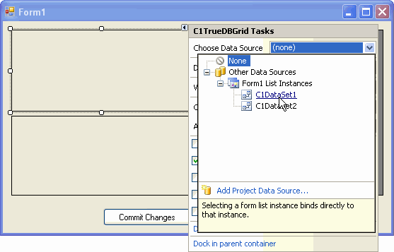
- Open the C1TrueDBGrid Tasks menu for C1TrueDBGrid1 and select C1DataSet1 under Choose DataSource.
- Set the Caption property to Customers.
- Open the C1TrueDBGrid Tasks menu for C1TrueDBGrid2 and select C1DataSet1 under Choose DataSource.
- Set the Caption property to Orders.
- Set the DataSource property of DataGridView1 to C1DataSet1.
- Set the Text property of Label1 to Employees.
- Set the DataMember property for each grid as follows and click Yes to replace the existing column layout:
- C1TrueDBGrid1.DataMember = _CustOrders
- C1TrueDBGrid2.DataMember = _CustOrders.CO - ODP
- DataGridView1.DataMember = Employees
Note: Data members exposed by a C1DataSet data source represent the TableView objects of the data set. Those that have child table views, or relations, can be used in a master-detail hierarchy. They are represented by two data members, one with a leading underscore, the other without it. The data member without a leading underscore is used to connect to the table view as to an isolated data source, without master-detail hierarchy. The data member with a leading underscore is used to connect to it as to the root node, or master, of a master-detail hierarchy. Dependent nodes, or details, are represented by relation names, such as _CustOrders.CO – ODP. - In order to be able to send data modifications to the database, double-click Button1 to create the Button1_Click event and add the following code to the event:
To write code in Visual Basic
Visual Basic Copy CodeC1DataSet1.Update()
To write code in C#
C# Copy Codec1DataSet1.Update();
- The second data set, ProductsOrders, will be shown in a separate form. Select Project | Add Windows Form, choose Windows Form in the Add New Item dialog box and click Add. Form2 is added to the project.
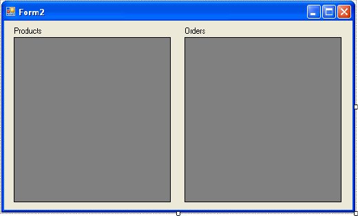
- Add two DataGridView components, DataGridView1 and DataGridView2, and two Label controls, Label1 and Label2 to the form.
- Set the the Text properties for Label1 and Label2 to Products and Orders, respectively.
The form will appear similar to the following:
- Add the following method to the Form2 code:
To write code in Visual Basic
Visual Basic Copy CodeFriend Sub SetDataSet(ByVal dataSet As C1.Data.C1DataSet) DataGridView1.DataMember = "ProductsOrderDetailsCust" DataGridView1.DataSource = dataSet DataGridView2.DataMember = "CustOrdersDetails" DataGridView2.DataSource = dataSet End SubTo write code in C#
C# Copy Codeinternal void SetDataSet (C1.Data.C1DataSet dataSet) { dataGridView1.DataMember = "ProductsOrderDetailsCust"; dataGridView1.DataSource = dataSet; dataGridView2.DataMember = "CustOrdersDetails"; dataGridView2.DataSource = dataSet; } - Go back to Form1 and add the following code to the Button2_Click event. This will activate Form2.
To write code in Visual Basic
Visual Basic Copy CodeDim form2 As Form2 form2 = New Form2() form2.SetDataSet(C1DataSet2) form2.ShowDialog(Me)
To write code in C#
C# Copy CodeForm2 form2 = new Form2(); form2.SetDataSet(c1DataSet2); form2.ShowDialog(this);
Run the program and observe the following:
- The two C1TrueDBGrid controls on the left show rows of composite tables CustOrders and OrderDetailsProducts combining data from multiple database tables. Note that this was achieved without creating database views or writing complex SQL statements with joins. It demonstrates how DataObjects for .NET is used to facilitate database application development, playing the role of a data modeling and query building tool. The most compelling benefits of the DataObjects for .NET's structured data model become apparent when you try modifying data. DataObjects for .NET does not merely present data as independent simple tables of rows. It maintains the specified structure automatically when you modify data – the task universally required in database applications and one that other data frameworks, including ADO.NET, fall short of supporting.
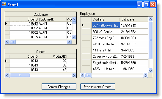
- To observe how DataObjects for .NET maintains underlying structure on data modifications, try changing the EmployeeID field in the first row of C1TrueDBGrid1, the Customers grid, from 6 to 1. The FirstName and LastName fields, dependent on EmployeeID, change correspondingly. Now go to DataGridView1, the Employees grid, and change the LastName of the employee with EmployeeID=1. All rows of the Customers grid that have EmployeeID = 1 reflect this change, showing the new LastName value. Alternatively, you can change the LastName or FirstName field in the Customers grid and see the change reflected in the Employees grid. Whatever the changes, DataObjects for .NET recognizes them so you can rely on proper structure being maintained for your data at all times.
- DataObjects for .NET supports master-detail hierarchy, as you can see in the Customers and Orders grids. The Orders grid shows the orders of the customer currently selected in the Customers grid. DataObjects for .NET also supports sorting: click a column header of a grid, and the data will be sorted by that column.
- In the Orders grid, you can see the ExtendedPrice column, which is a calculated field we defined in the schema.
- Try entering a negative number in the UnitPrice column of the Orders grid. Negative numbers are not allowed in accordance with the constraint we defined for the UnitPrice field of the Products table.
- Click Button2, the Products and Orders button. Form2 opens with two grids showing the two composite tables defined in the second data set of our schema, ProductsOrders.
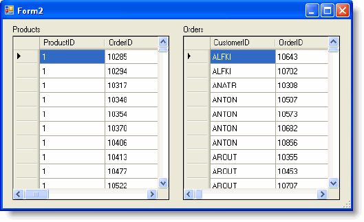
- Try entering a negative number in the UnitPrice column of the DataGridView2, or Orders grid, in Form2. Negative numbers are not allowed here as they are not allowed in Form1, because of the same constraint defined in the UnitPrice field of the Products table. This demonstrates a very important and powerful feature of DataObjects for .NET: business logic defined on table level is enforced in all composite tables and in all data sets where this table is used. You define business logic where it belongs, and do it only once, the rest is DataObjects for .NET's responsibility.