In Page Reports and Rdl reports, you can trace the layout of a pre-printed form to a pixel perfect accuracy using Layers.
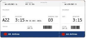
This walkthrough illustrates how you can trace data fields accurately from a scanned image of a boarding pass. These steps show the results on a Page Report but are applicable to Rdl Reports also.
Note: Right-click and save the image below in your project folder before starting the walkthrough.
The walkthrough is split up into the following activities:
- Adding an ActiveReport to a Visual Studio project
- Connecting the report to an XML data source
- Adding a dataset
- Creating a report layout on different layers
- Viewing the report
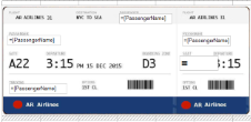
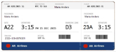
When you complete this walkthrough you get a layout that looks similar to the following at design time and at run time.
Design-Time Layout
Run-Time Layout
Adding an ActiveReport to a Visual Studio project
- In Visual Studio, create a new Windows Forms Application project.
- In the Solution Explorer window, right-click Form1, and rename it to MainForm.
- From the Project menu, select Add New Item.
- In the Add New Item dialog that appears, select ActiveReports 13 Page Report and in the Name field, rename the file to Boarding.
- Click the Add button to open a new Page Report in the designer.
Connecting the report to an XML data source
- From the Solution Explorer, open Boarding.rdlx created earlier.
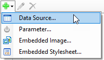
- In the Report Explorer, right-click the Data Sources node and select Add Data Source or select Data Source from the Add button dropdown.
- In the Report Data Source Dialog that appears, select the General page and in the Name field, enter a name like CustomDS.
- In the Type drop down to select a data provider, choose Xml Provider.
- In the connection string section, add the following custom data to your project.
Xml Copy CodeXmlData =
<Flight ID="31">
  <Passengers>
    <Passenger>
<PassengerName>Maria Anders</PassengerName>
<Seat>23A</Seat>
<Tracking>2322- 030-0074321</Tracking>
</Passenger><Passenger>
<PassengerName>Ana Trujillo</PassengerName>
<Seat>18E</Seat>
<Tracking>2322- 030-0074343</Tracking>
</Passenger><Passenger>
<PassengerName>Antonio Moreno</PassengerName>
<Seat>25A</Seat>
<Tracking>6722- 034-6784349</Tracking>
</Passenger><Passenger>
<PassengerName>Christina Berglund</PassengerName>
<Seat>14B</Seat>
<Tracking>5678- 543-6784349</Tracking>
</Passenger>
<Passenger>
<PassengerName>Thomas Hardy</PassengerName>
<Seat>28F</Seat>
<Tracking>9834- 413-6784569</Tracking>
</Passenger>
</Passengers>
</Flight> - Click OK to close the dialog box.
Adding a dataset
- In the Report Explorer, right-click the data source created in the previous step and select Add Data Set or select Data Set option from the Add button dropdown.
- In the DataSet Dialog that appears, select the General page and enter the name of the dataset as BoardingData.
- On the Query page, select Text under Command Type and enter the following XML path into the Query text box to access the data of each passenger.
//Passenger - On the Fields page, enter the values from the table below to create fields for your report. Values for XML data fields must be a valid XPath expression.
Field Name Type Value Tracking Database Field Tracking PassengerName Database Field PassengerName Seat Database Field Seat - Click OK to close the dialog. Your data set and queried fields appear as nodes in the Report Explorer.
See Adding a DataSet for more information on adding dataset to a data source.
Creating a report layout on different layers
- In the LayerList window, click the
 icon to add a new Layer to the report. Notice that a default Layer is already added in the Layer List.
 - Select Layer1 to make it the Active Layer, and from the Properties window, change the Layer Name to ImgLayer.
- In the Layer List window, check the Lock check-box to lock ImgLayer to make sure the image being traced is not modified or changed by mistake.
- In the Layer List window,click the Send To Back button to move ImgLayer behind the Default Layer.
- In the LayerList window, select Default to make it the Active Layer.
- From the Properties window, set the DesignerTransparency of the Default Layer to 0.5 to display the scanned image to be placed on ImgLayer in the background.
- From the toolbox, drag a List data region onto the design surface of the report.
- In the Properties window of the List data region set the following values.
Property Name Values DataSetName BoardingData FixedSize Width: 6.27in
Height: 3inLocation Left: 0in
Top: 0.125inSize Width: 6.27in
Height: 2.87in - In the Report Explorer window, right-click the Embedded Images node and select Add Embedded Image.
- In the Open dialog box that appears, browse to the project folder location and select the BoardingPass.jpg image you saved earlier.
- Click Open to embed the image in your project.
- From the Report Explorer, drag the embedded BoardingPass image onto the List data region and set the properties as described in the following table.
Property Name Property Value LayerName ImgLayer Location 0in, 0.125in Size 6.27in, 2.875in - From the Report Explorer, drag the following fields onto the List data region and set the following properties.
Field Name Property Values PassengerName LayerName: Default
Location: 2.91in, 0.35in
Size: 1.375in, 0.25in
PassengerName LayerName: Default
Location: 0.15in, 0.9in
Size: 1.37in, 0.25in
PassengerName LayerName: Default
Location: 4.5in, 0.9in
Size: 1.25in, 0.25in
Tracking LayerName: Default
Location: 0.15in, 2.19in
Size: 1.5in, 0.25in
Seat LayerName: Default
Location: 4.5in, 1.45in
Size: 1in, 0.375in
Font > FontSize: 22pt
- In the Layer List window, select the Default Layer and then the ImgLayer and change their TargetDevice property to Screen from the Properties window. See View, Export or Print Layers for more information.
Viewing the report
- Click the preview tab to view the report.
OR
- See Windows Forms Viewer to display report in the Viewer at run time.
See Also